Electronic Dice with ATtiny13

This electronic dice is powered from a CR2032 3V battery and an ATtiny13A microcontroller is controlling the LEDs. No button and no switch is needed to operate it. A piezo buzzer is used as a preassure sensor. I took it out from an old telephone. As the dice is dropped from at least 1 cm height to the table the dice shuffles through the numbers and after a few seconds it shows the rolled number.
Working principle of the dice
If you drop the dice, the piezo buzzer creates a voltage spike. This spike is trimmed by the 1N4148 diode so the microcontroller doesn't get damaged. This trimmed spike creates a pin change interrupt and resets a timer. In that moment another, always running timer is devided by 6 and the remainder of this division gives a number which is always between 0 and 5. 0 means 1 on the dice, 1 means 2 on the dice and so on. 5 means 6. So this number is the starting position of the dice. This number could be any number from 0 to 5, so basically it's a random number. From now on the numbers cycles through 1 to 6 fast and getting slower and slower, finally it stops on a number and this is the number you rolled with the dice. After a pin change interrupt has occured the pin change interrupt is disabled so you can not roll another number in the process.

The microcontroller has very few I/O pins, exatly 5. 1 is for the piezo input, so we have 4 I/O pins left. It is a challange to drive 7 LED-s with only 4 pins. The trick is that all 6 numbers of the dice can be put together with 4 patterns. Each number with maximum of 3 patterns.
Part list:
470R resistor x3 (R1, R3, R4)
1k resistor x1 (R2)
10k resistor x1 (R5)
1M resistor x1 (R6)
10 mm diffused red LED x7 (LED1, LED2, LED3, LED4, LED5, LED6, LED7)
1N4148 diode x1 (D2)
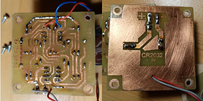
CR2032 battery holder x1
CR2032 battery x1
piezo buzzer x1
DIP-8 IC socket x1
ATtiny13A-PU x1 (IC1)
Single sided PCB 55x55 mm x2
15 mm M3 spacer x8
M3 8 mm pan head screw x4
M3 nut x4
M3 washer x4

resistor leg for jumper wire x2
some wire
all resistors are 1/4W
Schematic diagram

PCB Layout

PCB
Component placement top

Drill 3 mm holes in the plywood

Glue the piezo to the plywood with a hot glue gun

Insert the battery


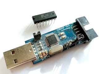
Programming the ATtiny13
Connecting the USBasp programmer to the uC.


It is the same process as I described in the previous post except here we put "t13" instead of "t84" in the codes:
test:
avrdude -c usbasp -p t13 -B 250
compile:
avr-g++ -g -Os -Wall -mcall-prologues -mmcu=attiny13 -fno-exceptions -o main_t13.obj main_t13.c
upload:
avr-g++ -g -Os -Wall -mcall-prologues -mmcu=attiny13 -fno-exceptions -o main_t13.obj main_t13.c
avr-objcopy -R .eeprom -O ihex main_t13.obj main_t13.hex
avrdude -c usbasp -p t13 -B 250 -U flash:w:main_t13.hex
THE CODE:
/*
Electronic Dice code for ATtiny13A-PU
fuse bits: (default fuse setting)
fuse high byte: 0xFF
fuse low byte: 0x6A
PINOUT
ATtiny13A
pin 1 RESET
pin 8 Vcc
pin 4 GND
pin 5 PB0
pin 6 PB1
pin 7 PB2
pin 2 PB3
pin 3 PB4
O..
... -> pin 3 PB4 pattern 1
..O
..O
... -> pin 6 PB1 pattern 2
O..
...
O.O -> pin 5 PB0 pattern 3
...
...
.O. -> pin 7 PB2 pattern 4
...
piezo -> pin 2 PB3
dice:
1 -> pat4
2 -> pat2
3 -> pat2 + pat4
4 -> pat1 + pat2
5 -> pat1 + pat2 + pat4
6 -> pat1 + pat2 + pat3
*/
#include <avr/io.h>
#include <avr/interrupt.h>
#include <avr/sleep.h>
#define F_CPU 1200000UL //cpu speed 1.2 MHz
#include <util/delay.h>
#define PAT1 1<<PB4
#define PAT2 1<<PB1
#define PAT3 1<<PB0
#define PAT4 1<<PB2
void setup_timer0(void);
void setup_io(void);
void en_pinchange(void);
void dis_pinchange(void);
void powerDown(void);
void display(uint8_t);
uint8_t msec=0, sleep=0, mix=0, num=6, tim=0;
/* MAIN ****************** MAIN *********************************/
int main(void)
{
cli(); //disable interrupts globally
setup_io();
setup_timer0();
en_pinchange();
sei(); //enable interrupts globally
PORTB &= 0b01000;
while(1)
{
if(mix==1)
{
if(sleep<2) num=tim%6;
else if((sleep>=2) && (sleep<4)) num=(tim/2)%6;
else if((sleep>=4) && (sleep<5)) num=(tim/4)%6;
else if((sleep>=5) && (sleep<6)) num=(tim/8)%6;
display(num);
}
if(sleep>8)
{
num=6;
PORTB &= 0b01000;
mix=0;
powerDown();
}
}
return 0;
}
/* MAIN ENDED *************** MAIN ENDED *************************/
/* ISR RUTINES ************* INTERRUPT ***************************/
ISR(PCINT0_vect)
{
sleep=0;
setup_io();
mix=1;
dis_pinchange();
}
ISR(TIM0_COMPA_vect)
{
msec++;
tim++;
if(tim>=192) tim=0;
if(msec>=20)
{
sleep++;
msec=0;
}
}
/* POWER DOWN ***************************************************/
void powerDown(void)
{
PORTB=0; //Set PORTB pins LOW
TIMSK0 &= ~(1<<OCIE0A); //Disable Timer0 OCMA interrupt
GIFR |= (1<<PCIF); //Clear eventually occurred previous pin change interrupts
en_pinchange();
MCUCR = (MCUCR | (1<<SM1)) & ~(1<<SM0);
MCUCR |= (1<<SE); //Enable Power-Down
sleep_cpu(); //CPU sleep!
MCUCR &= ~(1<<SE); //Disable Power-Down
sleep=0;
TIMSK0 |= (1<<OCIE0A); //Enable Timer0 OCMA interrupt
setup_io();
}
/* SETUP ******************************************************/
void setup_io(void)
{
DDRB = 0b10111; //Set PB0,1,2,4 pins to output, PB3 to input
}
void setup_timer0(void)
{
TCNT0 = 0;
TCCR0A |= (1 << WGM01); //CTC mode
TCCR0B |= (1<<CS02) | (1<<CS00); //Timer speed prescaler 1,2MHz/1024=1.172 kHz
OCR0A = 58; //interrupt every ~50ms
TIMSK0 |= (1<<OCIE0A); //enable Timer0 OCMA interrupt
}
/* PINCHANGE ******************************************************/
void en_pinchange(void)
{
GIMSK |= (1<<PCIE);
PCMSK |= (1<<PCINT3); // Set the pinchange input to PB3/PCINT3
}
void dis_pinchange(void)
{
GIMSK &= ~(1<<PCIE);
PCMSK &= ~(1<<PCINT3);
}
/* Numbers Subroutines *******************************************/
void one(void)
{
PORTB = PAT4;
_delay_ms(1);
}
void two(void)
{
PORTB = PAT2;
_delay_ms(1);
}
void three(void)
{
PORTB = PAT2;
_delay_ms(1);
PORTB = PAT4;
_delay_ms(1);
}
void four(void)
{
PORTB = PAT1;
_delay_ms(1);
PORTB = PAT2;
_delay_ms(1);
}
void five(void)
{
PORTB = PAT1;
_delay_ms(1);
PORTB = PAT2;
_delay_ms(1);
PORTB = PAT4;
_delay_ms(1);
}
void six(void)
{
PORTB = PAT1;
_delay_ms(1);
PORTB = PAT2;
_delay_ms(1);
PORTB = PAT3;
_delay_ms(1);
}
void display( uint8_t number)
{
if(number==0) one();
else if (number==1) two();
else if (number==2) three();
else if (number==3) four();
else if (number==4) five();
else if (number==5) six();
else PORTB &= 0b01000; //clear output pins
}
Youtube video:

Comments
Post a Comment